Gross pollutant trap (GPT)
Type: HumeGard model HG30A-R
Location: stormwater drain diversion point, 3 metres from the sedimentation chamber
Structure: concrete unit, installed separately
Pollutant capacity: 9.7 m3
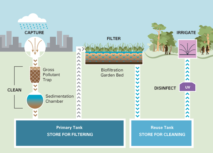
Purpose: the gross pollutant trap (GPT) is the initial screening device to remove gross pollutants and coarse sediments (greater than 150 microns) from the collected stormwater. The GPT is essential for the operation of the system because it prevents debris from entering the storage tanks.
In this system, the GPT removes approximately:
- 90 per cent of gross pollutants (litter, vegetation)
- 85 to 99 per cent of sediment
- 90 per cent of hydrocarbons
- 20 per cent of nutrients (phosphorus and nitrogen).
Maintenance: The GPT is inspected every three months and cleared of debris and silt/sand/gravel accumulation using a suction hose. A high-pressure jet can be used to clean the GPT, if required. Ideally, inspection and cleaning should take place after a major storm event.
The typical lifespan of a gross pollutant trap is 10 years and the replacement of this part has been factored into the maintenance budget.
Sedimentation chamber
Dimensions: nine metres deep, two metres wide and five metres deep
Structure: concrete, poured on site
Location: immediately next to the primary storage tank.
Purpose: The sedimentation tank collects and ‘settle out’ fine sands, sediments, oils and hydrocarbons that would otherwise accumulate in the primary tank. It is easier to access the sedimentation tank to clean away these pollutants than trying to clean the primary storage tank.
Maintenance: Once the accumulated sediment in the tank reaches a depth of two metres, the chamber is drained and the sediment removed using a suction loading truck.
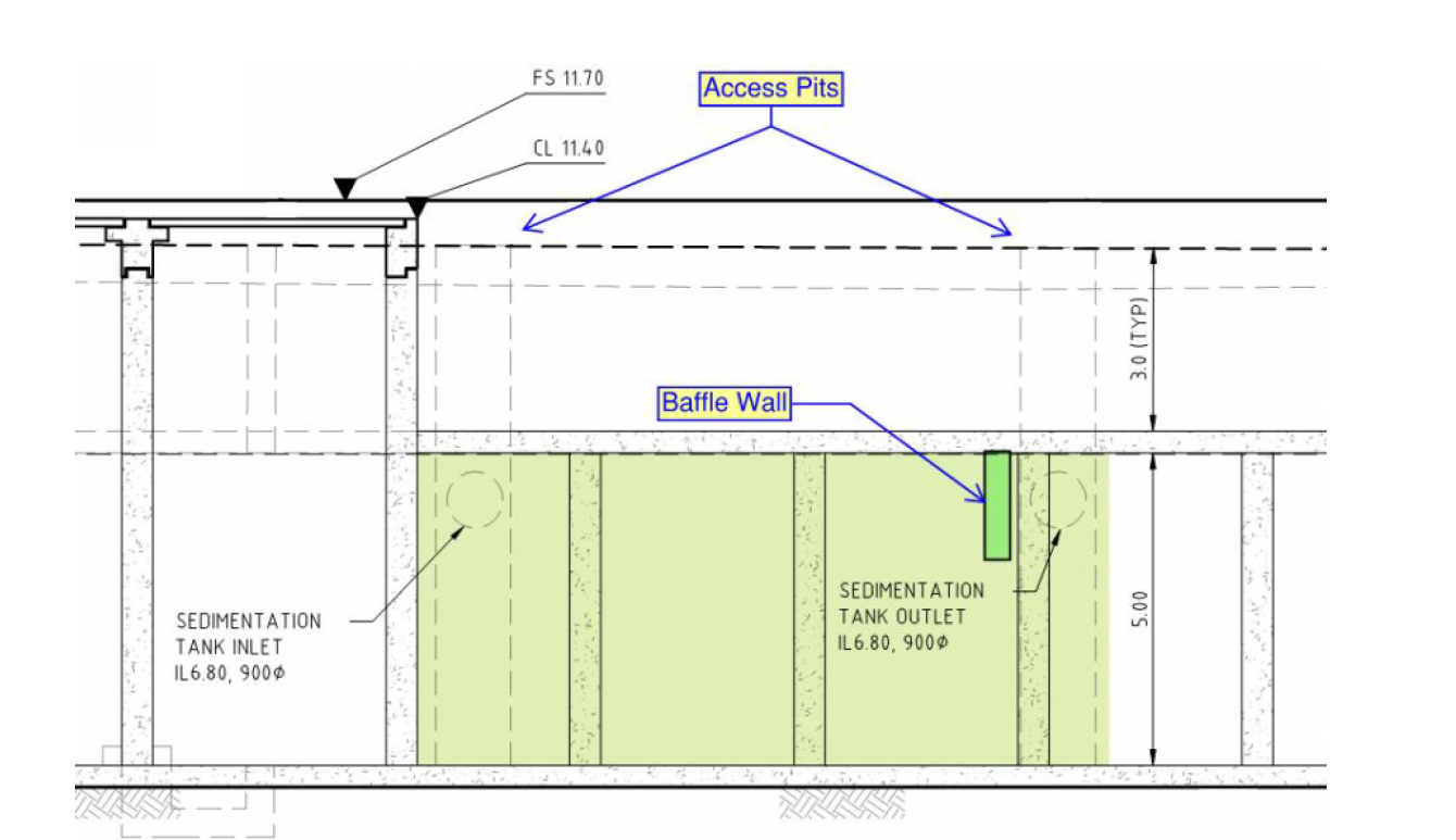
Section drawing of the sedimentation chamber
Dual tank system
Dimensions: 40.6 metres long, 25.6 metres wide, four metres high (internally)
Volume: Five million litres (four million primary tank, one million reuse tank)
Structure: Concrete tank poured on site.
The dual tank system is a large, oblong, underground tank with an internal dividing wall that creates two separate storage areas.
We used a dual tank system to ensure that flows of stormwater into the primary storage tank are not limited by the rate at which the biofiltration system can clean it. When it rains heavily the primary storage tank can take a large volume of water and gradually treat it through the biofiltration bed.
The design also allows for the secondary tank to be sized according to the irrigation needs of the park, rather than for the peak stormwater flow. This reduced the cost of the tanks.
We could have used modular plastic tanks for this system, but chose the structural stability of reinforced concrete because trucks need to regularly access the site.
The size and location of the underground storage tanks was influenced by the presence of heritage-listed buildings on site, which require buffer zones from construction areas.
Maintenance:
- Annually isolate all inflows and outflows and measure water levels (using dip stick) four times over 48 hour period to confirm no draw down and no leaks (and verify/calibrate level sensors readings).
- Drain tanks every five years to remove sludge and debris from (pump) sump pits using vacuum loading truck.
- Drain tanks after 50 years to access tank and remove sludge and debris and low pressure clean all wall and floor areas.
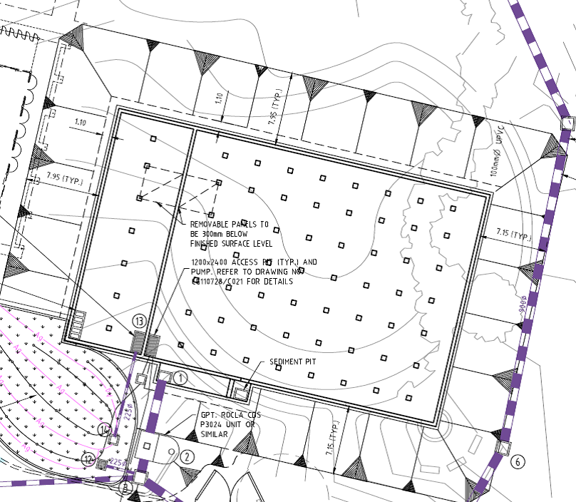
Plan drawing of the dual tank system
Biofiltration bed
Type: Biofilta system
Size: 241 m2
Maintenance: top layer of substrate replaced annually (using suction hose)
Purpose: To remove nutrients from the water (nitrogen and phosphorus)
The biofiltration bed was constructed the same way as a typical raingarden, with a sand filtration layer, a transition and a drainage layer. Unlike a raingarden however, the biofiltration bed is surrounded by a one-metre retaining wall. It is periodically flooded with water from the underground primary storage tank.
The flooding and resting cycle is based on the detention time of the water, which is determined by the hydraulic conductivity of the filter media. The cycle time is pre-set, but will be monitored and adjusted over time as the filter medium clogs and slows the detention time. Replacing the top of the filter media on an annual basis will renew the conductivity. The clean water drains naturally under gravity to the secondary tank where it is stored until needed for irrigation.
A wetland was considered as a treatment option for the system, but it was decided that bioretention would provide greater treatment capacity within the limited footprint of the site.
Plants
Species: Juncus gregiflorus and Juncus procerus
The top layer of the biofiltration bed was planted with ephemeral wetland plants. These native Australian grasses were pre-grown and installed in large format blocks to ensure fast establishment and high quality water within the first month.
Once per year, when the filter medium is replenished, the grasses are cut back to encourage vigour. Juncus have a clumping growth pattern at the base, which gives easy access to the suction hose that is used to replace the top layer of filter media. It is also a hardy plant that can easily withstand the slight disturbance of this process.
We consulted Heritage Victoria to ensure that the plants used in the biofiltration bed respected the heritage landscape of Fitzroy Gardens, while also enhancing the filtration properties of the sandy medium.
Pumps
Treatment system
Two Grundfos heavy-duty submersible pumps are located in a 580 mm deep sump pit at the base of the primary storage tank. These pumps transfer the untreated stormwater from the primary storage tank up to the biofiltration bed on the surface, via a rising main. Each pump has a duty of 40 litres per second.
Irrigation system
The irrigation pumping system consists of three primary vertical multi-stage submersible bore pumps and a single jockey vertical multi-stage submersible bore pump. The four pumps are located in a sump within the secondary storage tank.
The pumps deliver treated stormwater from the secondary storage tank to the irrigation ring main, via the tank services room for UV treatment. The pumping system is set to maintain a constant pressure of 900 kPa in the ring main.
The jockey pump delivers water to the visitor centre for toilet flushing.
Maintenance
In general, pumps and operation panels should be visibly checked for correct operation every month. Pumps should be raised, removed and delivered to an authorised pump servicing workshop for overhaul every five years or 3000 hours, whichever comes first.
The following tasks are completed on each pump annually:
- check for external corrosion or signs of wear
- check motor insulation resistance
- check motor current draw
- check for excessive bearing noise
- inspect oil seal and replace if necessary
- inspect cables for damage
- inspect pump inlets and clear any accumulated debris/build up or fouling objects.
UV filter
Type: Xylem Wedeco model LBX-200-U on line series UV disinfection unit with automatic wiping system and 3-phase ballast/control panel
The UV disinfection system is used to remove any remaining bacteria from the treated stormwater before it is used for irrigation. Located in the tank services room, the UV filter is controlled remotely by the IRRInet system.
Irrigation system
We operate an automated irrigation system in the Fitzroy Gardens. It distributes treated water from the stormwater harvesting system around the gardens via a large ring main. The ring main also receives drinking water to supplement the treated stormwater supply.
We use sensors in the tanks to record water levels. During times of low rainfall – when there is less stormwater being treated by the system – watering schedules are reduced to prolong the availability of alternative water.

